


3D printing workflow guide: from design to finished part
TL;DR:
- A 3D printing workflow is a sequence of steps that turns a digital model into a finished object. Mastering each stage reduces failures, improves quality, and saves time, regardless of the printer type.
A 3D printing workflow is the structured sequence of steps that transforms a digital model into a finished physical part. Mastering this process is the single biggest factor separating successful prints from wasted filament and failed builds. Whether you are a hobbyist running a desktop FDM machine or a professional producing functional prototypes, a consistent workflow reduces failures, improves part quality, and saves real time. Tools like Cura, PrusaSlicer, and Fusion 360 each play a defined role at specific stages. This guide covers every step in that sequence, with practical advice for getting each one right.
What are the main stages of a 3D printing workflow?
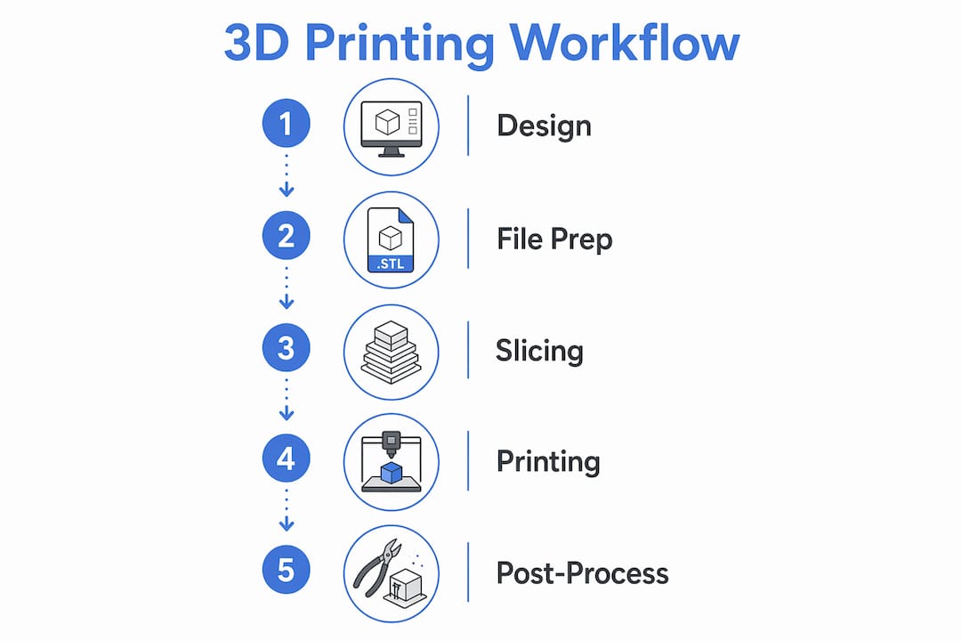
A standard 3D printing workflow follows six core stages: model, slice, print, post-process, and inspect. Each stage feeds directly into the next, so a mistake at stage two compounds by stage five. Understanding the full sequence before you start is what separates efficient makers from those who repeat failed prints.
The six stages break down as follows:
- Design the 3D model. Use CAD software such as Fusion 360, SolidWorks, or Tinkercad to create your part. Apply design for manufacturability (DFM) principles from the start, accounting for wall thickness, overhangs, and tolerances specific to your chosen printing technology.
- Export to a printable file format. Save your model as an STL, OBJ, or 3MF file. Each format carries different levels of data fidelity, which matters more than most beginners realise.
- Slice the model. Import the file into slicer software such as Cura or PrusaSlicer. The slicer converts your model into G-code, the machine instructions your printer reads layer by layer.
- Set up the printer. Load your material, level the build plate, and run any calibration checks. This stage is where most preventable failures originate.
- Execute the print. Monitor the first layer closely. A poor first layer almost always means a failed print.
- Post-process and inspect. Remove supports, wash or cure the part if required, and validate dimensions against your design intent.
Each stage has its own failure modes. Knowing them in advance is the foundation of any solid 3D printing workflow.
How to prepare your model and files for efficient printing
File preparation is the step most makers rush, and it is where the majority of print errors begin. Correct scale, orientation, and unit checks before exporting prevent mis-sizing and avoidable failures downstream. Spending ten minutes here saves hours at the printer.
Key file preparation steps:
- Apply DFM principles in CAD. Design for manufacturability can cut post-processing time significantly and reduce lead times by addressing additive manufacturing constraints at the design stage rather than after the print.
- Check orientation on the build plate. Orientation is often the single biggest workflow decision before slicing, as it directly affects support requirements, surface quality, and structural strength. Rotating a part by 45 degrees can eliminate most of its supports entirely.
- Choose the right file format. STL is the most widely supported format but carries no unit or colour data. 3MF files carry richer metadata including units and multi-material information, reducing ambiguity and file size through compression. For complex or multi-part assemblies, 3MF is the better choice.
- Validate your mesh. Non-manifold geometry, inverted normals, and open edges cause silent failures in the slicer. Tools like Meshmixer and Netfabb identify and repair these errors before they reach the printer.
- Minimise support structures. Fewer supports mean less print time, less material, and less post-processing. Reorient the model or split it into sub-components where possible.
- Use the slicer preview before exporting. A quick visual check in Cura or PrusaSlicer catches floating islands and unsupported regions that are invisible in the CAD view.
Pro Tip: Run your STL through Meshmixer’s Analysis tool before every import into your slicer. It takes under a minute and catches the geometry errors that cause mid-print failures with no obvious warning.
What slicing settings have the biggest impact on print quality?
Slicing is where your design intent becomes machine reality. The slicer converts your 3D model into G-code, a sequence of movement and extrusion commands that the printer executes line by line. Tuning these settings is the closest analogue to writing manufacturing specifications for your part.
The parameters that matter most, in order of impact:
- Layer height. Lower layer heights (0.1 mm) produce finer surface detail but increase print time substantially. For structural parts where appearance is secondary, 0.2–0.3 mm is the practical standard on FDM machines.
- Infill density and pattern. Infill controls internal strength without adding solid material throughout. Gyroid and honeycomb patterns distribute stress more evenly than rectilinear infill at the same density percentage.
- Support structures. Supports are necessary for overhangs beyond roughly 45 degrees, but they add print time and post-processing work. Tree supports in Cura and PrusaSlicer use less material than traditional block supports and are easier to remove.
- Print speed. Faster speeds reduce print time but increase the risk of layer adhesion failures and ringing artefacts on curved surfaces. Slow down for the first layer regardless of the speed set for the rest of the print.
- Orientation. Reconfirm orientation in the slicer, not just in CAD. The slicer view shows exactly how supports will generate and where layer lines will run relative to load-bearing directions.
G-code commands control nozzle paths, extrusion rate, and speed, making slicer tuning the primary lever for dimensional accuracy and material properties. Understanding what each G-code line does is not required for most prints, but knowing that the slicer is writing manufacturing instructions helps you treat its settings with appropriate care.
Pro Tip: Scrutinise the slicer’s layer preview from the bottom layer upward before every print. Floating islands and unsupported bridges are invisible in the 3D view but obvious in the layer-by-layer preview. Catching one before a four-hour print saves the entire session.
For a deeper look at tuning infill, layer height, and supports in Cura and PrusaSlicer, the filament printing setup guide at Subliblanks covers these parameters in practical detail.
What are best practices for printer setup and monitoring?
Printer setup is the stage where theoretical preparation meets physical reality. Bed levelling, material loading, and pre-print calibration are not optional steps to skip when you are in a hurry. They are the reason prints succeed or fail before the second layer is down.
Follow these setup and monitoring practices:
- Level the build plate every session. Even printers with automatic bed levelling benefit from a manual check when changing materials or after moving the machine. A 0.1 mm variance across the bed is enough to cause adhesion failure on one side.
- Load material correctly. For FDM printers, purge the previous filament fully before loading a new colour or material type. For resin printers, filter the vat before each session to remove cured particles that cause layer defects.
- Run a test extrusion. A short extrusion before the print starts confirms the nozzle is clear and the material is flowing at the correct temperature. This takes thirty seconds and prevents hours of wasted print time.
- Monitor the first layer. Watching the first layer identifies failures like poor adhesion or nozzle clogging early, allowing you to cancel the print before wasting material. The first layer is the single most informative indicator of whether the print will succeed.
- Keep the nozzle clean. Carbon deposits on the nozzle cause inconsistent extrusion. A cold pull with nylon filament clears most blockages without disassembly.
- Maintain a print log. Recording settings, material batch, and outcomes for each print builds a reference that accelerates troubleshooting on future jobs.
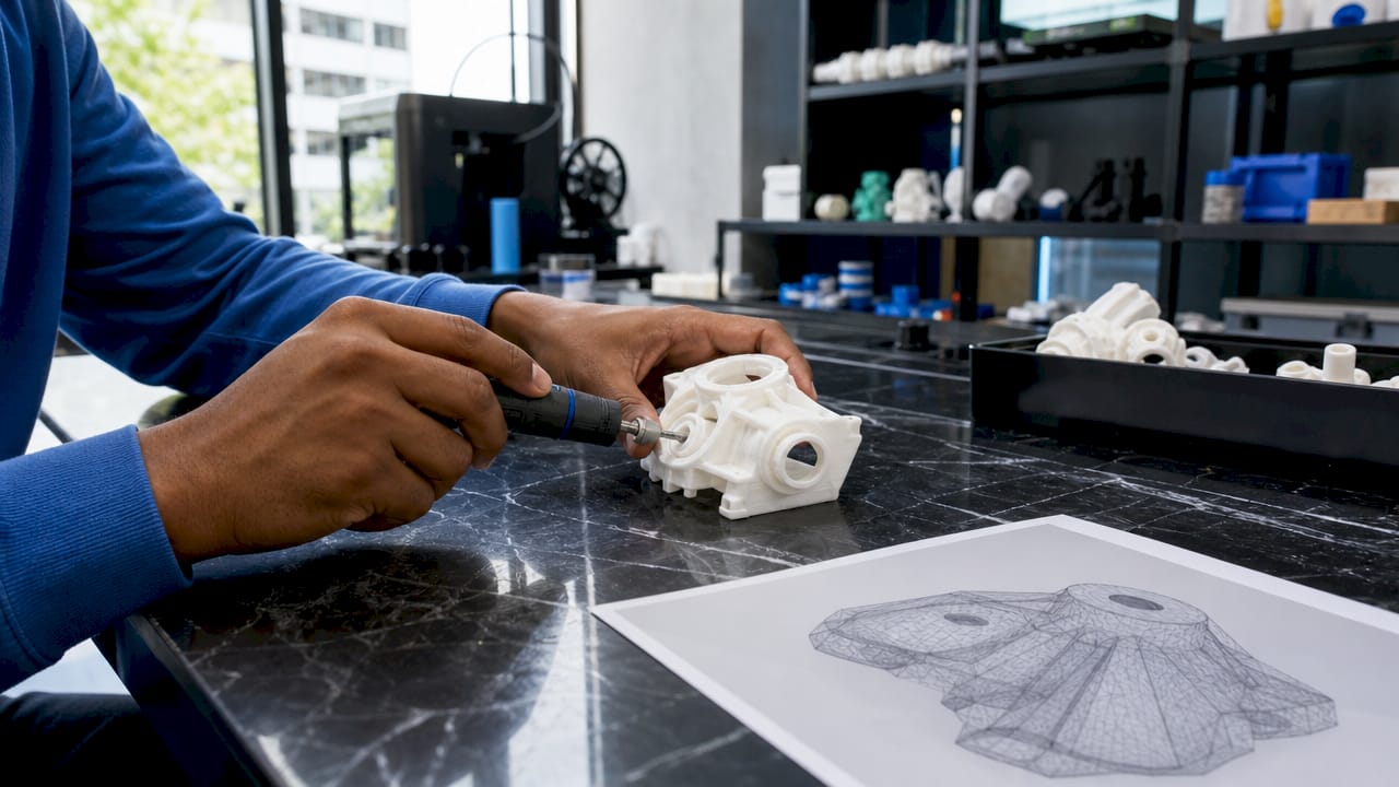
How to post-process and inspect your finished parts
Post-processing is not an afterthought. The finishing steps depend on printing technology and directly determine whether a part meets its functional and aesthetic requirements. FDM, SLA, and SLS each demand a different approach.
For FDM parts, the standard process is support removal followed by sanding. Start with 120-grit sandpaper and work up to 400-grit for a smooth surface. Acetone vapour smoothing works specifically with ABS filament and produces near-injection-moulded surface quality, though it requires ventilation and care.
For SLA resin parts, washing in isopropyl alcohol removes uncured resin from the surface, and UV curing hardens the part to its final mechanical properties. Skipping or shortening the cure time leaves parts brittle and tacky. Formlabs recommends specific wash and cure times for each of their resins, and those figures are worth following precisely.
For SLS powder-bed parts, depowdering removes loose powder from internal channels and surfaces. Bead blasting improves surface finish and reveals dimensional accuracy for inspection.
- Sand progressively. Never jump from 120-grit to 400-grit in one step. The intermediate grits remove the scratches left by coarser paper.
- Test function before finishing. Check fit, thread engagement, and load-bearing performance before applying paint or coating. Finishing a part that fails functional testing wastes time.
- Validate dimensions. Use digital callipers to check critical dimensions against the CAD model. A 0.2 mm offset on a press-fit feature is the difference between a part that works and one that does not.
Pro Tip: For FDM parts that need a smooth finish without sanding, apply a thin coat of UV-cure resin and cure it under a UV lamp. The resin fills layer lines and sands to a near-perfect surface in a fraction of the time.
For a step-by-step breakdown of the full process from a beginner’s perspective, the beginner’s 3D printing guide at Subliblanks covers each stage with practical examples.
Key takeaways
A successful 3D printing workflow depends on treating every stage, from CAD design to final inspection, as a quality gate rather than a formality.
| Point | Details |
|---|---|
| Design for the process | Apply DFM principles in CAD to reduce supports, post-processing time, and failures. |
| Choose the right file format | Use 3MF over STL for complex or multi-material parts to preserve unit and metadata accuracy. |
| Tune slicing settings deliberately | Layer height, infill pattern, and orientation are the primary levers for quality and print time. |
| Monitor the first layer | A poor first layer predicts a failed print; cancel early to save material and time. |
| Match post-processing to technology | FDM, SLA, and SLS each require different finishing steps to achieve functional and aesthetic results. |
Why the workflow matters more than the printer
Most makers I speak with blame the printer when prints fail. The machine is rarely the problem. After years of working with FDM, SLA, and SLS processes, the pattern is consistent: failed prints trace back to a skipped step in the workflow, not a faulty machine.
The most common error I see is rushing file preparation. A model exported without a mesh check, or oriented without considering where layer lines will run under load, will produce a poor result on even the best hardware. Cura and PrusaSlicer are powerful tools, but they cannot fix a broken mesh or a badly oriented part. That work happens upstream.
The second most common error is treating slicing as a one-time setup. Slicer profiles need revisiting when you change filament brands, switch nozzle sizes, or move to a different material type. A profile tuned for PLA at 0.2 mm layer height is not a starting point for PETG at 0.15 mm. Treating it as one is how you get warping, layer separation, and wasted spools.
The good news is that every stage of the workflow is learnable and improvable. The makers who get consistent results are not the ones with the most expensive printers. They are the ones who treat each stage as a discipline, keep print logs, and iterate methodically. That approach works on a £200 desktop machine just as well as it does on a professional system.
— chris
Subliblanks: filaments and resources for your printing projects
Subliblanks supplies a full range of 3D printing filaments alongside equipment and accessories for makers, hobbyists, and professionals at every level. Whether you are refining your first workflow or scaling up production, having reliable materials makes every stage of the process more predictable.

Subliblanks operates with no minimum order quantities, so you can test new filament types without committing to bulk stock. The Subliblanks blog covers workflow guides, material comparisons, and setup advice to support your projects from the first layer to the finished part. Visit subliblanks.com to browse filaments, equipment, and the full range of printing supplies available for trade and hobbyist orders.
FAQ
What is a 3D printing workflow?
A 3D printing workflow is the structured sequence of steps from digital model creation through slicing, printing, post-processing, and final inspection. Each stage feeds into the next, and skipping any one increases the risk of print failure.
Which file format is best for 3D printing?
3MF is the preferred format for complex or multi-material parts because it carries unit data, colour information, and metadata that STL does not support. STL remains widely compatible and is acceptable for simple single-material prints.
How do I reduce failed prints?
The most effective approach is to validate your mesh before slicing, check orientation carefully, and monitor the first layer of every print. Catching failures early at the first layer allows you to cancel and restart before wasting material.
What slicer software should I use?
Cura and PrusaSlicer are the two most widely used slicers for FDM printing and both are free. Cura offers a large plugin library and broad printer compatibility; PrusaSlicer provides strong support for multi-material setups and detailed layer preview tools.
Does post-processing differ between FDM and SLA?
FDM parts typically require support removal and sanding, while SLA parts need washing in isopropyl alcohol followed by UV curing. Post-processing steps depend on printing technology and skipping any step reduces the part’s mechanical performance and surface quality.


